
For this video demonstrating the range of motion of a valve, I created several 3D motion graphics elements. An outer ring shows the arc of the handle, while “sunburst” arms represent regular divisions of the various possible settings that the valve can be turned to in order to control the flow of water. The sunburst arms are scaled one after another in sequence as the valve handle sweeps over them, so they extend from “within” the axis of the valve to the outer arc.
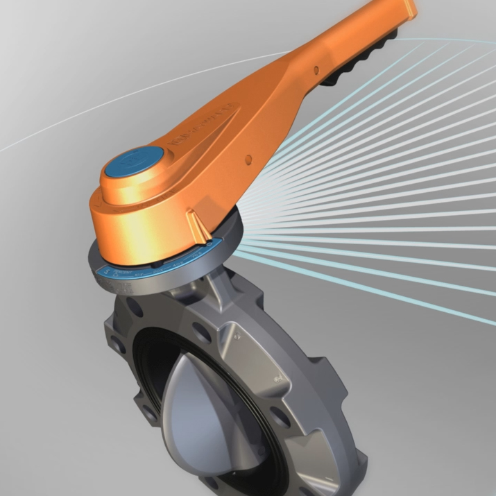
This diagrammatic geometry was rendered as a separate layer that could be placed above the background but underneath the valve in the compositing software, where its opacity could also be keyframed.

This model was adapted from .iges and .stl CAD files provided by the manufacturer.
Since these meshes are designed for manufacturing, they’re often excessively dense for the purposes of animation, requiring a cleanup process that maintains the integrity of the model. Excessively dense geometry can not only increase the rendering time, it can produce some unpredictable results with the behavior of light and shadows on the model’s surfaces – at times creating a pinched or otherwise textured appearance in areas that are supposed to be perfectly flat.
The pivots and related rigging aspects need to be attended to with special care to ensure realistic model behavior, balanced with the need to provide for exceptionally clear, demonstrative animation. In the above still, the interlocking teeth of the valve needed to be shown in action in a visible way – a scenario that would be impossible to see with live action footage.
The valve can only be open and closed when the safety handle is engaged; the model was rigged to accommodate this factor with set-driven keys that managed all of these elements simultaneously.
Shaders representing various materials including textured plastic and brushed metal were created and applied to the imported and adapted models based on RGB values derived from the manufacturer’s reference photos.

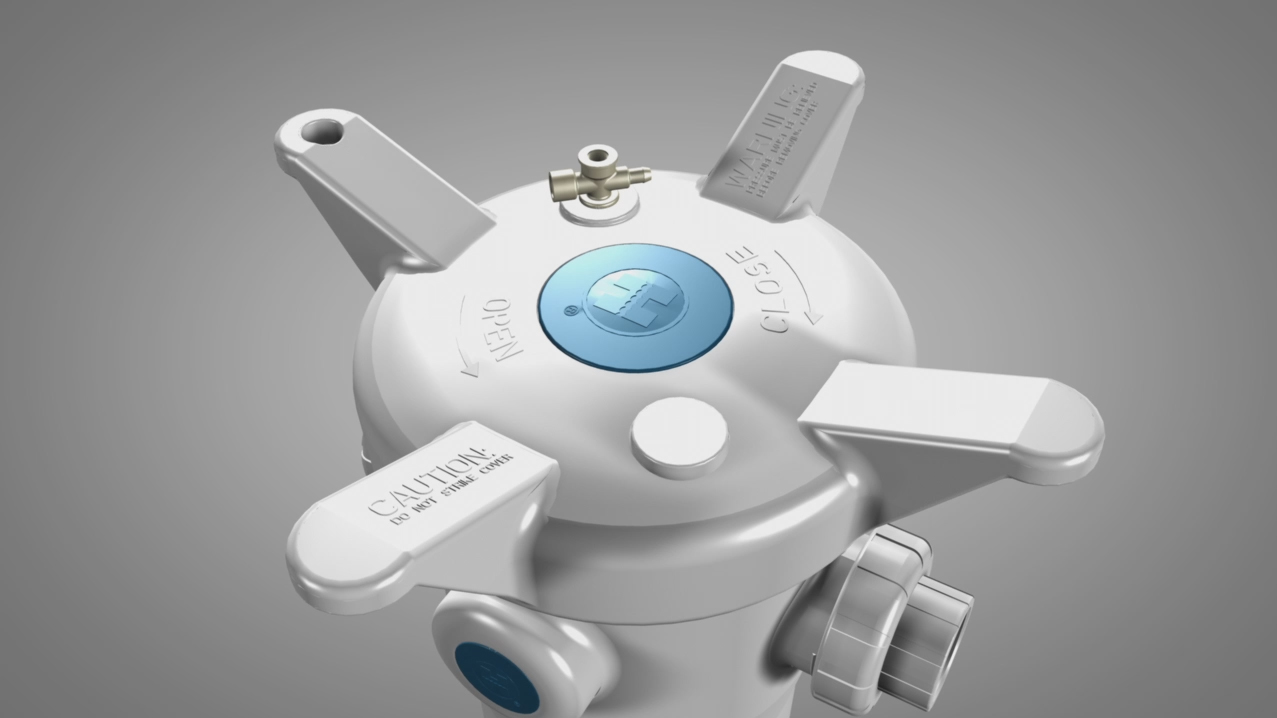
A complex, multi-part set of CAD models was required for a demonstration/informational video of a water filter.
The models were imported from .iges and .stl files, producing NURBS meshes within Maya. Each surface area produced a separate patch with visible gaps. Because the product needed to be viewed with extreme closeups, the gaps had to be repaired. The NURBS meshes were converted to polygons, and vertices were merged where gaps were visible. In the case of especially complex surfaces, like the basket inside the filter, it was more efficient to rebuild the model from scratch rather than repair the imported file. https://player.vimeo.com/video/120081950
The model then had to be textured to provide the appearance of the various real-world materials composing the filter parts. It was also rigged and pivot points were set for the necessary rotations and translations of each part.

The model was then arranged according to design documents and each component was assigned to individual render layers, allowing for cutaways and masked dissolves to be coordinated in the compositing stage.
A background clip designed for additional image overlays. The images are “pushed forward” by the flow of water and particles. The particles are designed with rim lighting to evoke the appearance of imagery derived from an electron microscope.
The particles are composed of geometry controlled by dynamic particle emitters, with various speed, spread and rotation values. There are also bitmap textures applied to flat planes that are produced by particle emitters – these have two of their rotation channels locked so they can’t be seen to be flat, though they can still rotate on one axis to match the behaviors of the geometry particles.

The clip loops seamlessly after about 20 seconds so the client can extend it as needed. The loop was created by having discrete start and end keyframes for the group of particle emitters. The image sequence was rendered from before the emitters began, until after they stopped and the last particle left the frame. Then the image sequence was duplicated and overlayed in compositing software, with the timing offset to maintain an apparent continuous particle flow.
To save 3D rendering time, a Z-depth channel was rendered and depth of field effects were applied in compositing.
